Random Thoughts on Wave 2 / MU-MIMO

I’m writing this on an airplane while headed to the heart of Wi-Fi, Silicon Valley. These are some random thoughts so please bear with the lack of formatting and general disregard for the English language. I’m not a Lee Badman or Marcus Burton or Ben Miller that can just pound out an award winning essay in short order.

Multi-User MIMO is fancy new technology to enable an access point to transmit to multiple client devices simultaneously. Pretty cool stuff. But why? Many mobile devices only support 1 spatial stream (SS) and at best, 2 SS. So if you have a bad ass AP that is 4×4:4 but all of your client devices are 1×1:1 you paid WAY too much for an AP. MU-MIMO fixes that. With that introduction to MU-MIMO, here are some thoughts.

#1 

There is no Wave 1 or Wave 2. There is no standard for either. It was invented to delineate between first and second generation of 11ac. It is generally accepted that Wave 2 includes support for MU-MIMO. We (marketing people) have to put a label on it and when MU-MIMO APs hit the street we’ll call them Wave 2. Just remember that its a made up term with no real standard.

#2 

Why is there a third number representing the capabilities of a MIMO AP? 2×2:2. 3×3:3. Well, its because the third number hasn’t always been the same as the first two. First gen 11n was 3×3:2. Cisco has a 4×4:3. When it comes to flat-out speed, the last number (spatial streams) is the most important. So the max data rate of a 4×4:3 and a 3×3:3 is exactly the same.

There is another variable with 11ac – how many multi-user streams an AP supports and it won’t always be the same as spatial streams. Why is that? More on that later.

But because of that, I have proposed a new nomenclature to indicate number of MU streams; adding a 4th digit. For example, 4×4:4:3.

– 4 Transmit Chains
– 4 Receive Chains
– 4 Single-user Spatial Streams
– 3 Multi-user Spatial Streams

Now, I don’t have any skin in the game whether this is adopted or not. But its an easy way to show capabilities.

#3 

MU-MIMO requires client support. Look for them to start hitting the street by Q3 2015.

#4 

With regards to radio technology, single-user MIMO and multi-user MIMO are basically the same thing. Both require the AP to do some bad ass math to decorrelate the signals so they look different to each receiving antenna. Whether the receiving antennas are on one device (SU-MIMO) or on multiple devices (MU-MIMO) doesn’t really matter. The really smart people that think of this kind of thing knew this could be done a long time ago.

So why is MU-MIMO just now happening? First, it requires feedback from the clients. It was difficult enough to get clients to support explicit TxBF feedback. Second, the MAC had to be figured out.

#5 

The MAC is whack. One of the greater challenges with MU-MIMO is how the MAC is going to be handled. So, every time a device transmits (unicast) it requires an ACK. A Wi-Fi device can either transmit or receive but never both at the same time. So, the AP transmits three unicast transmissions at the same time. The ACKs CANNOT all come back to the AP at the same time or you have a collision. MU-MIMO doesn’t work in the upstream. So you have to delay some ACKs etc. Frames are varying sizes. Frames are sent at varying data rates. This is getting complicated.

#6 

Each MU stream can be a different MCS (data rate) but cannot be different Tx power. As MCS goes up, legal Tx power goes down. (Why is beyond the scope of what I have time to type right now. I have a PPT I’m supposed to be working on. Google PAPR). So if one client can Rx at MCS 9 but another can only Rx at MCS 7, the Tx power has to be the lowest of the two (MCS 9). BUT, if the power is lower than MCS7 would normally be. Is it enough power for the other client at MCS 7? Or, should the rate have dropped down to a lower MCS? I know that sounded really confusing. Here’s the summary: Proper rate selection will be a HUGE differentiator among vendors.

#7 

Keys to MU-MIMO performance: Rate and group selection. Before a Wi-Fi device transmits it must determine the fastest rate it can successfully transmit to the receiver. Too slow and its wasting air time. Too fast and the STA won’t receive properly and will have to retry. Mix this with the power problem in thought #6 and an AP has its hands full figuring out the proper data rate.

Before a MU-MIMO AP transmits to multiple clients it must look at the list of all clients that need data at that moment. Next, it has to choose the right combination of client devices where the AP can successfully decorrelate (make look different) the signals for each client.

MU-MIMO gets more efficient with more clients spread out over a larger area because it has more selection freedom.

#8

MU-MIMO is a bandage and generally kinda sucks. SU-MIMO (regular MIMO) is perfectly efficient. If you go from 2×2:2 to 4×4:4 you get double the performance. MU-MIMO has so many efficiency problems that you don’t get nearly the same benefits. If it were possible to make a 4×4:4 mobile phone MU-MIMO goes away.

#9

Transmit beamforming will go away. Once your network has the bulk of the clients MU capable, why would you ever use precious AP Tx chains to gain 3-6 dBs? You won’t. As much as MU-MIMO sucks, TxBF is worse. Sorry about that.

#10

In #4 I mentioned that SU and MU-MIMO are basically the same thing. There is one major difference though; point of view. A 4×4:4 AP can send 4 streams to a 4×4:4 client all day long. BUT, a 4×4:4 MU-MIMO AP can only select 3 MU clients at the same time. Why the contradiction? Because a receiving 4×4:4 client can correlate all four signals it “sees”. It can compare them to each other, do some PhD math and get all four data streams. However, if you are sending MU data to multiple clients, they cannot compare each signal to each other. They lack the perspective that each STA has. As an aside, this is why MU-MIMO requires client feedback but SU-MIMO doesn’t.

You WILL see vendors touting a 4×4:4:4 AP in the future. My employer will be one of them. However, the 4th MU stream is luck. 3 streams can be controlled and IF it works out that the 4 “lands” on a client that needs data, 4 MU streams could be sent. The likelihood of this happening increases as client count and client to client distance increases.

As an aside, I can already see TMEs (Technical Marketing Engineers) in a lab walking around with a mobile phone trying to figure out how to get 4 MU streams. 🙂

So will you see test that show a 4×4:4:4 AP sending 4 MU streams? Sure. Will you see it in real life? We shall see but the math says 3 MU streams is all you will really get.

Conclusion

This technology is so complicated that an entire blog could be written on every aspect of it. I hope this helps clear up some myths and misinformation. Would love to hear comments and questions.

GT
@gthill

RF Myths

One of the greatest things about working for Ruckus is that I get to work with so many smart men and women. And we have a plethora of them that are experts in radio frequency, which is why I have learned some myths that I had wrong for so many years. So it’s with that I present you some of my favorite RF Myths.

Myth #1 – Signals Interfere With Each Other

Imagine two signals from two different sources (APs for example) on the same channel colliding in mid-air. We tend to envision waves traveling through the air. And we have been told that if two signals are opposite of each other they are canceled. Well, it doesn’t work that way.

Two signals traveling through the air on the same frequency have zero effect on each other. Imagine you are holding two flashlights (torches for you English types). They both have color filters on them with one shining a blue light and the other yellow. If you shine them on the wall you see their respective colors. Now what happens if you cross the streams Does it change the colors on the wall? No, of course not. This is because they have no effect on each other as they pass through the air.Ghostbusters

But what if you pointed both lights at the same place on the wall? The colors would mix into green. Signals don’t interfere with each other but, two or more signals that arrive at the same receiver mix and this is interference. Signals and interference are always from the perspective of the receiver. Signals traveling through the air have no effect on each other.

Myth #2 – Low Frequency Signals Travel Farther Than High Frequency

We’ve all heard that low frequency RF travels farther than high frequency but it just isn’t true. And right now you are thinking I’m crazy but hear me out.

First, picture in your head two signals of equal power traveling through space. One is a much higher frequency than the other. If they both have the same power, does it make sense that one would fizzle out before the other? This is exactly what Victor Shtrom (Ruckus co-founder) said to me. And I was like… no. That doesn’t make sense.

So let’s explore this further. If you’ve worked around RF before you KNOW that low frequencies work at farther distances. And you’d be right. Wait. Isn’t that contrary to this myth? No, there is a distinct difference. Lower frequencies have a longer effective range but it isn’t because high frequency signals get weaker faster. It’s because of something called aperture size.

The term wavelength is literally the length of one cycle of a wave. If you like math you can see it here (link to Wiki article). Frequency is just how often something happens. In this case it’s how many times a wave completes a full cycle in one second. For 2.4GHz, a wave completes a cycle 2.4 billion times per second. Sounds like our National debt. Anyway, for something like CB radio that operates at 27MHz the wave only cycles 27 million times per second. Given that all radio travels at the same speed (speed of light) the length of the wave is directly correlated to frequency. That is, the lower the frequency, the longer the wave.

Antennas are designed for a specific frequency; a specific wavelength. Many antennas are designed at ¼ wavelength intervals. Why is beyond the scope of this blog but feel free to Google antenna design to your hearts content. A 2.4GHz wavelength is just over 12cm in length. So if you design an antenna for 2.4GHz you’ll space your elements 3cm apart. If we start talking antenna gain, we look at how many of those elements there are. Generally speaking, the more elements that are lined up properly, the higher gain of the antenna. Heinrich_Rudolf_Hertz

Let’s compare that 2.4GHz antenna to a 27MHz antenna. The wavelength at 27MHz is 11 meters. We are still going to design for ¼ wavelength so that means each ¼ wavelength is 2.75 meters long! Stay with me, we’re almost there. Let’s say we design both antennas to have 3, ¼ wavelength elements.

That means the 2.4GHz antenna is 9cm long and the 27MHz antenna is 8.25m long. So, why do lower frequencies have a longer effective range? Given the same exact design parameters, the antennas are bigger. Yes, you read it right. Lower frequency antennas are bigger. They have more surface area (aperture) to capture the signal so they hear more of the energy.

Myth #3 – Two Wi-Fi Signals Received Simultaneously Results in a Collision

Noise and interference are sometimes regarded as the same thing but they are actually quite different. Noise is signal that always exists; it even exists in nature. But interference is from an active transmitter such as a cordless phone, Bluetooth device or even Wi-Fi.
SNR
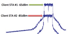
All Wi-Fi performance is directly related to Signal to Interference + Noise Ratio (SINR). Ideally you want as much signal vs. interference as possible (to a point). When two Wi-Fi signals arrive to the client at the same time, as long as one is sufficiently stronger than the other, the stronger of the two signals will be deciphered and processed. How much stronger depends a lot on the chip itself, but if there were a 20dB difference the stronger signal would be received and deciphered perfectly. The weaker signal just gets treated as noise.

The Wi-Fi That Never Was

I’ve been fortunate enough to be in the Wi-Fi industry for close to a dozen years now. To a point, having 12 years (vs 4 or 5) doesn’t really help much except that you can reflect on things of yesteryear and hope to sound cool (and old) doing it.

There were quite a number of technologies that were introduced as either a Wi-Fi amendment (or parts thereof) that were never implemented by Wi-Fi vendors. This is by no means a comprehensive list. I’m saying that because for the most part this is from memory and I know I missed something so I needed some kind of out. Ok, on with the list. 

Implicit Beamforming

As one of the many, many enhancements brought to us by 802.11n, beamforming is one that has been talked about much be never been fully realized (11ac fixes that).

In order for beamforming to work properly it has to know how to phase the transmissions to the client. The more accurate the channel information, the more accurate the beamforming will be.

There are two types of beamforming that were specified in 802.11n. Explicit beamforming is the better of the two but requires that the client device support explicit beamforming. Up until 802.11ac, there were no client devices that supported this so it never saw an 11n implementation.

Implicit beamforming does not require client support but has had very mixed results. Cisco is the only company that ever implemented it on the APs (ClientLink) but every test I’ve ever seen doesn’t put it in a good light. That really isn’t Cisco’s fault; implicit beamforming has now been shown by every chip manufacturer to just not work well. Because of that it was decided that implicit beamforming would not go into the 802.11ac amendment.

802.11F Inter-Access Point Protocol (IAPP)

The goal was simple: Standardize communication on the distribution system (typically Ethernet) during the client roaming process. That would enable an AP to forward client information, buffered data etc to the new AP over the wire.  

The real coolness was that it would not only enable a client to roam between APs seamlessly, but between two different vendor APs.  Who the heck would want to do that? Well, the answer was (mostly) no one. From memory, Proxim was the only vendor to implement IAPP.  Heck, if I were them I’d want to interoperate with other vendors too. How else could they expect to get market share?

802.11F was standalone document (denoted by the uppercase F) and never gained traction. It was ratified in 2003 but was officially deemed dead in 2006.  Sorry about that.

802.11T (Wi-Fi Performance Prediction)

Potential Wi-Fi customers hear pitches from every vendor and every one of them includes some sort of test showing them being the fastest thing on the market. But who is a customer to believe? The IEEE tried to solve this problem by establishing a standard for testing Wi-Fi.

The goal was to enable testing and comparison of Wi-Fi systems based on a standard set of performance metrics and testing procedures.  The amendment made it through a significant portion of the process but died before it was completed. The amendment committee is made up of members that also work for Wi-Fi vendors. In this particular case, members of the committee (representing vendors) couldn’t come to an agreement and the amendment was never ratified.

Point Coordination Function (PCF)

The Wi-Fi we know and love today is based on Distributed Coordination Function (DCF) which is a fancy way to say that Wi-Fi is pure anarchy.  

From my observations most people new to Wi-Fi think that the AP is in charge and controls the network. Depending on your point of view this is unfortunately not the case. APs and clients are on equal ground when it comes to accessing the communication medium (the air).

However, there once was a protocol that had it differently.  The “point coordination” part of PCF really means “access point coordination”. PCF put the AP in charge by telling a client when it could and couldn’t talk.  Think token ring for Wi-Fi. This isn’t a lettered amendment that can just be blindly ignored or deleted. PCF has always been (and still is) in the standard but never used as a contention mechanism.

HCCA (Hybrid Coordinated Channel Access)

When 802.11e (QoS) was introduced in 2005 it introduced a significant number of protocol additions to Wi-Fi. Originally, QoS was going to fall within 802.11i (Security) but it was split out when it was realized that both topics were very complicated.

The two main methods for achieving QoS in 802.11e are EDCA (Enhanced DCF Channel Access) and HCCA. EDCA is a math-modified version of the contention system that has been used since Wi-Fi’s inception. It is how QoS is done today. HCCA was a modified version of PCF Mode (see above) that allowed a weighted system for calling on the client STAs. The AP would know which devices were voice, video best effort and background and it would call upon them in an efficient manner to guarantee those access categories. Guarantee is an interesting word there because EDCA cannot guarantee a class of service; it can only give statistical probability to each access category.

I have to give mad props to my man Ben Miller. He told me very early on that HCCA was never going to be implemented. I didn’t really understand why because it was, at least from a QoS perspective, superior to EDCA. But sure enough, about a year later the IEEE removed HCCA from 802.11e.

It’s been fun to think back about all the stuff that we had to learn (Thanks Devin!) but never really got to put to good use… until now.


GT

Buckle down. Learn Wi-Fi. Get paid.

A young kid (ok, 22) came out to my place the other day to hook me up to DirecTV. I got to talking to him about his career and future plans. He presented himself very well; smart, courteous and knew that he didn’t know everything but was willing to learn. I thought to myself… give me six months with this guy and I could triple (maybe quadruple) his salary.

Why? Because Wi-Fi is one of the hottest technologies out there and we are lean for great people. Marcus Burton and I frequently discuss the need for more solid Wi-Fi people and the conversation usually ends in frustration because we need the help but can’t find the pool of talent.

There is a need and any strong vendor will pay for talent. A lot. Most of you reading this are most likely in the field already but for those of you that aren’t… A Wi-Fi SE starts at $120k and I know of some making $200k+ with commissions. No degree required but bet your ass there is plenty of study.

None of us out there started out as Wi-Fi experts. I used to deal poker and Wi-Fi friends of mine used to be TSA agents, car salesman and many are prior enlisted military. Nothing against those professions but they seldom offer $120k+ salaries, stock options and benefits. Wi-Fi does.

What does it take? First off, you do need a certain aptitude for technology. I find that most people can actually fit that role if they are properly introduced to the fundamentals. Second, you need to be able to lock yourself in a room and learn. Read, watch videos, play with the equipment, configure, capture, analyze, rinse, repeat.

It also will really fast track your Wi-Fi career if you get certified. Come to any of us in the industry with your CWNA, CWAP and CWDP and if you don’t get a job it’s because you cheated on the exams or reek of roasted garlic and rotten milk. Customers have to like to be around you after all.

If you or someone you know is looking for a career change, look no further. It could be the best move you’ve ever made.

GT

The Balanced Link Fallacy

Having a set of walkie talkie radios as a kid was the ultimate in cool toys. Well, except for my TI-99/4A. Anyway, just like every new plaything, we found the limit of our new form of communication very quickly. Once we reached a three or four hundred yards away from each other we weren’t able to understand each other any longer.  Bummer.

Those walkie-talkies are a great example of a nicely balanced link. They were identical; both had the same transmit power, antenna and receive sensitivity.

Transmit Power

Transmit power is the amount of power that the radio chip actually produces. Power output from a Wi-Fi device is typically measured in milliwatts (mW) or dBm. A 200 mW (23dBm) transmitter is pretty decent in a Wi-Fi access point.

Antenna

The antenna is responsible for taking the power from the chip and sending it out on to the air. Antennas typically provide gain is signal strength although they don’t have to. In the world of Wi-Fi, antennas are typically measured in dBi. Those nice rubber duck antennas that you see give about 3dBi of signal gain.

Receive Sensitivity

This is lesser known of the three factors in our link. Receive sensitivity is how well a device can hear. My wife repeatedly tells me that I’m a good listener. (“Sorry babe, what did you say?”) That means I must have good receive sensitivity.  Receiver sensitivity is typically shown in an RSSI (Received Signal Strength Indicator) chart. This chart states at what signal level a certain data rate can be achieved. Here is a made up truncated chart:

Device #1

-87dBm = 6Mbps

-84dBm = 18Mbps

-73dBm = 300Mbps

Device #2

-85dBm = 6Mbps

-83dBm = 18Mbps

-70dBm – 300Mbps

Device #1 has better receive sensitivity because it requires less signal to achieve the same data rates as device #2. (keep in mind that these numbers are negative so the closer to zero is higher.)

Defining Balance

An imbalanced link is when one device can hear better or transmit higher signal than the other. For example, let’s say that my set of walkie talkies had a “signal gain” dial on it. My brother sets his to 5 and I turn mine up to 11. Now I’m transmitting more power than him and we have an imbalanced link.

Is this link imbalance a problem? Before we answer that, let’s look at the link itself. What defines a good link with our walkie talkies? That’s pretty simple. If each party can understand the other, we have a good link. Oddly enough, this analog link is quite binary in nature. Either you can understand each other or you can’t.

When do you consider that the link failed? The link has failed when there is no longer bi-directional communication. The purpose of walkie talkies is to communicate with each other (two way) not like a radio station (one way). So, for the link to be considered broken, only ONE side of the link has to fail.

Back to the question. Is the link imbalance between our walkie talkies a problem? No, it actually isn’t. All it means is that at a certain distance, bi-directional communication will fail. The fact that one transmitter is higher than the other doesn’t actually matter. This is exactly what happens in a Wi-Fi network.

Have you ever stopped to think about what actually transpires in a Wi-Fi network when a client device can no longer communicate with an AP? I guarantee you, 99.999% of the time it’s ONE side of the link that fails first. If a device transmits and never receives an ACK, the link has failed.

Many a tech document has stated that if you want Wi-Fi to work right, you should lower the transmit power of the AP to the match that of the client. That is a terrible idea. Stream of consciousness as to why:

– The AP has much better receive sensitivity than your client. If you set the Tx power on the AP to 30mW equaling that of the client BUT the AP can hear 6dB better, you still have a seriously imbalanced link.

– Ah… now you are thinking this: If I set my Tx power of my AP to compensate for the client hearing better, now I have a balanced link. What that means is, you set the AP Tx power to 6dB higher than the Tx power of the client. Now, your AP would be transmitting at 120mW (6dB higher) and your client at 30mW. Now you have a balanced link! Perfect! Well, not really.

Bring on the meat!

Some vendors like to use dynamic (non static) antenna gain and / or transmit beam forming (TxBF) to get more signal to the client. But, if the client can’t talk any louder, does that actually improve anything? Read on!

Walkie talkie communication was quite simple. Again, we could either understand each other or we couldn’t. But, Wi-Fi brings in another factor that doesn’t exist in analog communication. Data rates.

Wi-Fi automatically adjusts data rate to accommodate the communication channel. If signals are high and everything is good, it transmits at high data rate. If there is noise and signals are weak, it will transmit at a low data rate. (There are a bunch or rates in between too) With Wi-Fi, signal equals speed and reliability. Unless you are at your maximum MCS (data rate) extra signal will improve your link speed and that equates to improved capacity and throughput.

So what happens if you have that evil unbalanced link and your AP sends higher signals than your client?  Great! I’m digging that because it gives me increased data rates on ALL downlink data. Given that many networks have 80%+ of their data going to the clients from the AP, who wouldn’t want more signal, speed, capacity and throughput?

Looking Beyond the Room

For those of you that don’t follow Devin AkinJared Griffith or Jeanette Lee on Twitter… let me give you an update. 

Effectively it is being argued that Ruckus technology (adaptive antennas, ChannelFly etc) has no effect on performance in a classroom environment because all of the 30+ iPad devices in the classroom are limited by their downstream throughput which is about 25Mbps. In Aerohive’s “Need for Speed” blog they state that these iPad consume about 80% of the airtime even though they are moving at relatively slow speeds by today’s standards. I haven’t personally tested this but I believe these numbers. 

Now, my response.

First off, I work for Ruckus and this blog is Ruckus centric. I’ll try to not make a habit of it. Promise.  

One of the things that I have stressed with all of my Wi-Fi students over the years is to look at a Wi-Fi network as a whole organic structure. Understanding the protocols and RF between an AP and a client are essential but the next step is to understand how each Wi-Fi device (STA or AP) effects each other. We don’t live in a world with one AP. 

High Density Myth #1: Adaptive Antennas (BeamFlex) doesn’t help the throughput of an iPad. 

True (yes, you read it right). If you test one iPad with one AP within 10 feet of each other in a clean environment, you’ll probably get similar results from most vendors including Linksys and Netgear. Unfortunately for those vendors, that situation only exists in poorly thought out tests.

BeamFlex is an adaptive antenna technology that customizes signals in both direction and polarity to optimize the signal for the client device. That is what BeamFlex is most known for anyway. However, one of the significant but unsung benefits of adaptive antennas is the reduction of co-channel (AP to AP) interference.

Imagine that you install one AP per classroom like is recommended by most vendors. Now you have a multitude of APs within close proximity of each other. If they follow their standard channel plan of 1,6,11 then you will have significant co-channel interference because you bought too many APs. And, don’t give me that crap about reducing transmit power for “smaller cells”. That only works so so and if you reduce the transmit power enough to make a real difference then you reduce the data rate to the client devices creating a new host of problems. 

Signal control while maintaining appropriate transmit power reduces co-channel interference while keeping data rates high. 

High Density Myth #2: Channel selection is simple

The “standard” channel plan is to use 1,6 and 11 and change channels when some arbitrary measurements hit a pre-determined threshold. Ruckus invented a technology called ChannelFly that works off of a very simple measurement. Capacity. Each AP selects the channel that gives it the best possible throughput and network capacity. It’s secret sauce how this happens but it really makes a difference. Don’t trust me, try it in real life (I hate lab environments). 

High Density Myth #3: More clients equals more APs

One of the most common and significant mistakes in Wi-Fi network design is installing too many APs. Ask any independent Wi-Fi consultant and they’ll tell you that they have, at some point in their career, turned APs off in order to improve the network. Is one AP per classroom appropriate? Only in limited cases. Many factors must be present before I recommend one AP per classroom. Many vendors arbitrarily and consistently recommend this and I do not agree with this practice. 

My Invitation

More than likely you will test each vendor’s Wi-Fi gear before you buy. I highly encourage it. However, here is what I ask of you. If you want to test one AP in a classroom that is fine but if you want to see real results, test in as real of an environment as you can. Install 6+ APs, stress them all and observe the overall network performance. 

Each vendor puts focus on solving a different problem. Some problems are real and some aren’t. Ruckus is the Ferrari/Lamborghini/McLaren F1/Bugatti/Ducati of the Wi-Fi world because that is where we put our focus. Ruckus has more Wi-Fi engineers than Aerohive, Xirrus, Meru and Meraki combined. Ok, I made that up (blogs do that) but I bet I’m not far off. 🙂

GT

Happy Birthday Paradox!

Disclaimer

I’ve read over my own words here and I thought that it would be good to insert a disclaimer. It isn’t normal for me to talk about a complex topic without some context but unfortunately I need to here because this is a blog and not a book. However, here are a few links that should provide some context if the subject of contention is new or a bit rusty. The first is a paper written by Marcus Burton. The second is the full meal deal, the CWAP book. Enjoy!

Now for the Beginning

The birthday paradox, also known as the birthday principle is a math equation that calculates probability of two people in a group having the same birthday (day/month). As an example, to guarantee that two people in a group have the same birthday you’d need 367 people because there are 366 possible birthdays.

Here is where I’ve earned myself some extra cash on the side and dazzled many an intoxicated onlooker. Let’s say there are 30 people in the room. I put $100 on the table and tell you that I’ll bet that two people in this room have the same birthday. Your gut tells you that you should take that bet but you are hesitant because I sound so confident. Keep your money in your pocket because I would have a 70% chance of winning. Yes, with only 30 people in the room there is a 70% chance of a duplicate birthday. This isn’t because people don’t want to go outside in the winter either. It’s all about the math. In fact, with only 23 people there is a 50.7% chance of duplicate birthdays. Why? Well, I’ll let you click the links above because I want to get somewhere Wi-Fi-ish with this blog and lots of math is a surefire way to get people to stop reading. 🙂

If we can assume for a minute that birthdays are randomly distributed then that makes for a great analogy to Wi-Fi. Wi-Fi uses a randomly generated number system called a random backoff timer to help avoid collisions . This is the basis for a system called contention. Two or more devices “contend” for access to the medium.

The Wi-Fi Paradox

The question is, what are the chances that a collision will occur? First, we need to know the number of possible “birthdays”. Before a device transmits regular data (not voice or video) it will randomize between 0 and 15. That give us 16 different possible choices. With that known, what are the chances of collision with x number of devices?

2 – 6%
3 – 18%
4 – 33%
5 – 50%

What that means is that if there are 4 devices contending for the medium there is a 33% chance of collision. Better stated, if you had that as a persistant situation, your network would have a 33% collision rate. That is of course unacceptable and would make for a poor Wi-Fi network.

For the life of me I can’t figure out where to conclude this thing. This is one of those discussions that will have a lot of rabbit holes and I can’t figure out when I’ve said enough. Good thing I love to talk because my writing is horrible.

Anyway, I think this deserves a follow up at some point. For now I want to leave you with a few questions to ponder on:

– Is it actually feasible and common that 4 or 5 devices would be contending with each other simultaneously (in the same contention windows)?
– Our example used the number 16 but what would happen if the randomization is with fewer numbers such 8 or 4?
– Will varying frame sizes make a difference in the collision rate?

GT

Talk faster and not so loud…

… I’m in a hurry and my head is pounding.

Ever read something a dozen times only to notice something completely new the 13th time around? Not too long ago I was perusing some boring vendor specs (chances are it was ours) and noticed something on the transmit power specs:

– 6 Mbps | 23 dBm
– 9 Mbps | 23 dBm
– 12 Mbps | 23 dBm
– 18 Mbps | 23 dBm
– 24 Mbps | 23 dBm
– 36 Mbps | 22 dBm
– 48 Mbps | 20 dBm
– 54 Mbps | 19 dBm 

As the data rate increases, the maximum transmit power decreases. I’ve actually observed this before but I never stopped to think of why. Why does the transmit power decrease? 

I’m quite fortunate that I work for a company like Ruckus. I can walk into Bill Kish’s office (uber genius CTO) and ask him this very question. Instead of trying to put things in my own words and looking like I’m some smart guy, I’m going to start by quoting Bill: 

OFDM backoff due to high peak to average power ratios of higher OFDM modulations.

OFDM signals are more challenging to amplify since with all the subcarriers you sometimes get ‘unlucky’ combinations of the values on the different subcarriers which results in high peak signal strength.  These high peaks would cause the amplifier to go non-linear, distorting the signals.  Sorta like ‘clipping’ in an audio amplifier.

This effect gets worse with higher order modulations.  So two things: for OFDM you need to turn down power compared to e.g. CCK and furthermore you need to turn down power even more for each higher order modulation.   Good radio design and good PAs (power amplifiers) can reduce this effect but not really eliminate it.”

I ran this through the GT translator and this is what popped out:

Let’s imagine that you have an audio source (e.g. your phone) connected to an amplifier and speakers. During slow, soft music (e.g. 1 Mbps CCK) everything is fine. However, when you start playing faster music like techno and house mixed together (OFDM) the chances of “too much music” coming out of your source and overpowering your amplifier increases. As the music gets faster and chances of a peak increase, the input volume to the amp needs to be reduced to avoid clipping. This is the very reason why AP manufactures sets decreasing transmit powers for higher OFDM modulation rates.

When any manufacturer tells you their maximum Tx power and EIRP that is almost always for the lowest data rates. Sure, that helps you just fine if you are trying to gain more coverage but coverage isn’t the main concern for most enterprise installations. Throughput and capacity are paramount. 

What’s the best way to compensate for this Tx power loss at higher speeds? Antennas.

Resisting… sales…. pitch…. 

🙂

GT

RTS/CTS. Request to Send / Clear to Send. But, don’t remember what it stands for because it’s lying to you.

RTS/CTS is one of those protocols that is widely misunderstood. At face value it appears that it’s job is some sort of “negotiation” to determine if it’s ok to talk. It reminds me a bit of my kids. “Dad, can I ask you a question?” Well, you just did dear. 🙂

“Requesting” to send is a bit of the same thing. A Wi-Fi device has to send send a frame to… request to send? No, it doesn’t do that. I truly don’t want people to know or remember what RTS/CTS stands for because it is misleading.

RTS/CTS has nothing to do with requesting access or clearing the way. If you don’t believe me, well, there is nothing I can do to help that.

Ok, you’re a believer. Read on.

RTS/CTS has the same function as toast. Yeah, like hot browned bread just out of the toaster. No one (except the English I think) eat toast plain. Americans eat toast with butter and preferably with butterand jelly. So, what is the toast good for? To carry your butter and jelly. Now, if truth be told, many of us would rather just eat the butter and the jelly out of the jar but civilized people don’t do that so we drowned some brown bread in loveliness and call ourselves sophisticated.

The purpose of toast is merely a carrier for butter and jelly. RTS/CTS is just a carrier as well. It carries something called a duration value. A duration is quite simple. It’s an amount of time that we want everyone in receiving range to stay quiet. Why do we want them to stay quiet? Because Wi-Fi is anarchy and anything that can be done to fix that can be helpful. Ok, that wasn’t as in-depth as you may have liked. Go here to see one problem it can solve: http://en.wikipedia.org/wiki/Hidden_node_problem.

When a device receives any frame (including RTS/CTS) with a duration value >0 (duration values are in microseconds) it will set something called a NAV timer. If you’ve never heard of this don’t fret. It’s just a fancy way of saying “countdown timer”.

Simply put, if any device hears a duration value, it sets it’s NAV and stays quiet at least that amount of time. Wish I could do that during family outings.

What’s the difference between an RTS and a CTS? Have you ever played Marco Polo as a kid? Someone says Marco and what do you do? You say Polo. If an RTS frame is sent to you (RTS’s are always unicast) the you MUST respond with a CTS frame. RTS frames have space for two addresses and CTS frames have space for one.

RTS and CTS frames are used quite often in Wi-Fi so when you are sniffing a network (www.sniffwifi.com) and you see them just remember that they are there to help your network. Or a denial of service attack. Ah, I love Wi-Fi. 🙂

GT